|
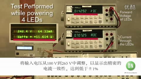
Powerint公司的15W LED驅動器采用LinkSwitchTM-PH LNK417EG器件和±3% CC調整,具有高效率,功率因素大于0.9,AC輸入電壓90V-265V,滿足IEC 61000-4-5環形波, IEC 61000-3-2 Class C諧波和EN55015 B接觸EMI要求,起動時間小于100ms.本文介紹了該驅動器主要特性和指標, 驅動器和子板電路圖以及相應的材料清單與PCB布局圖. This document describes an isolated, power factor corrected, very high efficiency LED driver (non-dimmable) designed to drive an LED string of 30 V at a current of 500 mA(both nominal) from an input voltage range of 90 VAC to 265 VAC. The design employs a secondary side current feedback circuit to achieve less than 3% output current regulation over line and load. A reference board DER-284 was used with the secondary constant current regulation daughter board added to demonstrate how this technique can be used on and LinkSwitch-PH flyback design. The LED driver uses a LNK417EG device from the LinkSwitch-PH family of ICs. This integrated controller and 725 V MOSFET dramatically reduces complexity and omponent count. This document contains the LED driver specification, schematic, and bill of material,transformer documentation and typical performance characteristics. 15W LED驅動器主要特性: ≤3% output current regulation over line and load Highly energy efficient Efficiency ≥88% at 115 VAC and 230 VAC input Low cost, low component count and small printed circuit board footprint solution Frequency jitter for smaller, lower cost EMI filter components Integrated protection and reliability features Output open-circuit / output short-circuit protection with auto-recovery Line input overvoltage shutdown extends voltage withstand during line faults. Auto-recovering thermal shutdown with large hysteresis protects both components and printed circuit board No damage during brown-in or brown-out conditions Meets IEC 61000-4-5 ring wave, IEC 61000-3-2 Class C harmonics and EN55015 B conducted EMI Clean start-up – no output blinking Fast start-up (<100 ms) – no perceptible delay 
圖1.15W LED驅動器外形圖 15W LED驅動器指標:
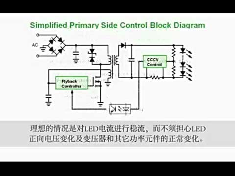
圖2.15W LED驅動器電路圖
圖3.15W LED驅動器子板電路圖
圖4.15W LED驅動器PCB布局圖
圖5.子板PCB布局圖 15W LED驅動器材料清單:
子板材料清單:
圖6.變壓器電路圖 詳情請見:  der289.pdf
(3.11 MB)
der289.pdf
(3.11 MB)
|